


Waterjet Cut Quality Troubleshooting: Taper, Striations, Wide Kerf and Poor Edge Finish
A rough edge is not a diagnosis by itself. The location and shape of the defect—at the top, through the wall, at the bottom, or only around corners—help reveal whether the first check should be cutting speed, standoff, abrasive delivery, pressure stability, wear parts, alignment, or motion control.
Start With Evidence, Not a Guess
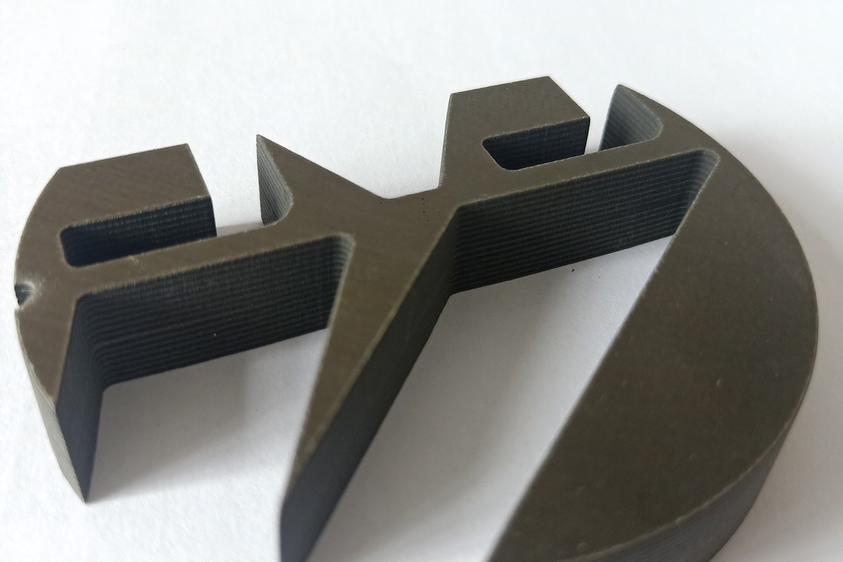
Waterjet cut quality is the combined result of the high-pressure water stream, abrasive condition and feed, orifice and mixing-tube condition, cutting-head alignment, nozzle-to-workpiece distance, material and thickness, programmed speed, motion behavior, and part support. Different faults can leave similar marks. For example, heavy lower-wall striations may appear when the feed rate is too high for the available jet energy, but a pressure loss, interrupted abrasive flow, or a worn focusing tube can also reduce effective cutting performance.
Before making an adjustment, save a baseline. Record the material grade and actual thickness, pump pressure during the cut, orifice and mixing-tube sizes, abrasive mesh and feed setting, standoff, programmed quality or feed rate, head type, pierce method, cut direction, and where the defect occurs. Photograph the top edge, bottom edge and full cut face. If a previously stable job has changed, compare the present setup with the last known good result.
How to Read a Waterjet Cut Surface
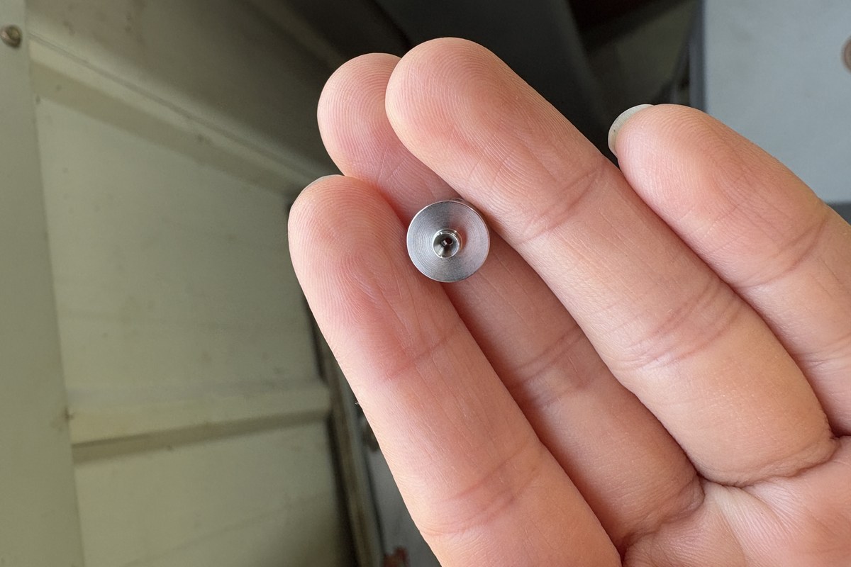
An abrasive waterjet does not behave like a rigid milling tool. The stream can bend as it moves through material. The entrance region may look relatively smooth, while waviness and jet lag become more visible lower in the cut as speed rises relative to the available cutting energy. The depth where a smoother surface changes into a visibly striated surface is often described as the transition zone.
Top edge and entry
Look for rounding, frosting, chipping, excessive washout or an oversized entry. These signs can point toward excessive standoff, an unsuitable piercing strategy, material movement, or a stream that is already spreading before it reaches the workpiece.
Middle of the wall
Check whether the wall is straight and whether the surface pattern is consistent. A sudden change can indicate process instability; a consistent angle may be normal taper or compensation that is not correctly matched to the job.
Lower wall and exit
Heavy curved lines, bottom burr, a narrow exit or an incomplete cut usually justify checking feed rate versus available jet energy, actual pressure, abrasive delivery and the condition of the cutting head.
Corners, arcs and holes
If straight edges are acceptable but corners or small holes are not, focus on motion dynamics, acceleration and corner control, lead-in strategy, tool offset, calibration and whether taper compensation is correctly applied.
Diagnose the Symptom Before Changing Parameters
1. Excessive taper
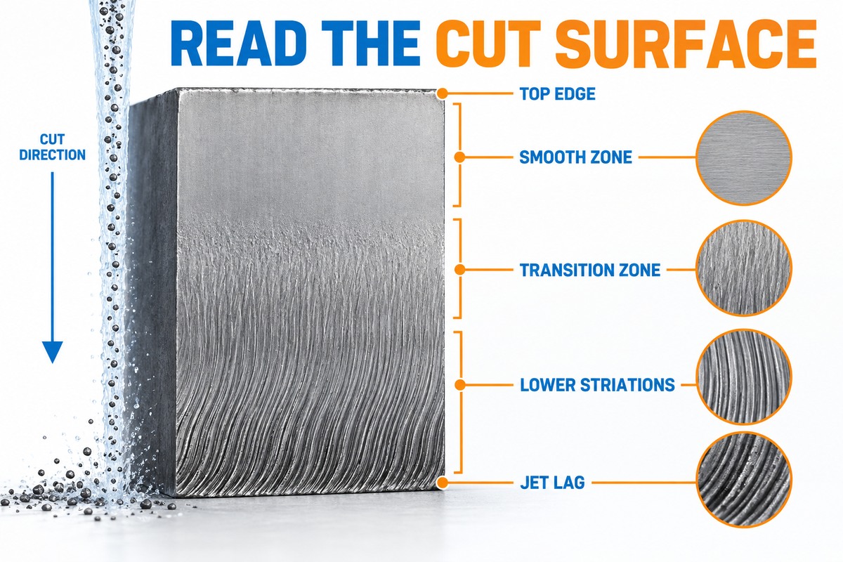
Taper is the difference between the cut width at the top and bottom of the workpiece. Its direction and amount depend on material, thickness, abrasive, standoff, feed rate, stream condition, geometry and compensation strategy. A standard 3-axis head may leave natural taper, especially when production speed is prioritized. A properly calibrated 5-axis or taper-compensation head can tilt the stream so the finished edge is closer to square, but it cannot correct an unstable jet, worn consumables or incorrect process data.
First confirm that the material and thickness entered in the software match the actual workpiece. Check that the nozzle is not farther from the surface than required by the machine process. Inspect the orifice, mixing tube and their alignment, then verify the correct tool offset and head calibration. If hardware and setup are sound, use the manufacturer’s cutting model or reduce feed according to the required edge quality.
2. Heavy striations or excessive jet lag
Curved lines that become stronger toward the bottom often indicate that the cutting head is advancing faster than the stream can cut cleanly through the material. However, “slow down” should not be the first and only response. Confirm that the commanded pressure is being reached and remains stable under load. Check for a consistent abrasive stream, dry abrasive, correct abrasive metering and an unobstructed feed path. A damaged orifice, worn mixing tube, misalignment or a leak can reduce effective energy even when the program has not changed.
3. Wide or changing kerf
A kerf that is wider than the established baseline, changes along the path, or produces inconsistent dimensions may indicate mixing-tube wear, stream misalignment, excessive standoff, pressure variation or unstable abrasive delivery. Because focusing tubes wear gradually, dimensional drift may appear before a dramatic edge defect. Measure the kerf with the same test material and method, compare it with the recorded baseline, and update the tool offset only after confirming that the hardware is serviceable. Software compensation should not be used to hide a damaged wear part.
4. Bottom burr, attached material or incomplete separation
When the stream has insufficient remaining energy at the bottom of the workpiece, material may remain attached or form a rough exit edge. Possible causes include excessive feed rate, pressure loss, interrupted or insufficient abrasive flow, incorrect material data, a worn cutting-head component, increased standoff, or a section that is thicker or harder than expected. Stop and inspect rather than repeatedly running the same failing program; an incomplete cut can also allow the jet to deflect unpredictably.
5. Rough top edge, chipping or piercing damage
Top-edge damage is often related to entry conditions. Verify standoff and make sure the workpiece is flat and supported. Brittle or laminated materials may need a controlled low-pressure, circular or edge-start piercing strategy supported by the machine manufacturer. Place pierces and lead-ins in scrap areas where possible, and avoid assuming that a pierce routine suitable for steel is automatically suitable for glass, stone or a composite.
6. Poor corners, small holes or inconsistent geometry
The jet must slow and change direction around corners, while the lower portion of the stream may lag behind the nozzle. If defects are concentrated around small radii or holes, check whether the controller’s material model and corner strategy are active, whether the machine motion is smooth, and whether the part is securely supported. On a compensation head, confirm calibration and nozzle orientation. Do not increase compensation until the basic jet and consumable condition have been verified.
Fast Troubleshooting Reference
| Observed symptom | Likely contributors | First checks | Do not do first |
|---|---|---|---|
| Top wider than bottom | Natural taper, feed rate, standoff, material/thickness data, compensation setup | Confirm actual material and thickness; inspect standoff and wear parts; verify calibration and quality setting | Do not add arbitrary head angle before checking the process model |
| Heavy lower striations | Feed too high for available jet energy, pressure loss, inconsistent abrasive, nozzle wear | Check actual pressure under load, abrasive delivery and focusing-tube condition | Do not change several parameters together |
| Kerf becomes wider | Mixing-tube wear, misalignment, high standoff, pressure or abrasive fluctuation | Inspect the water-only jet and wear parts according to the manufacturer procedure; measure a standard coupon | Do not compensate only by changing tool offset |
| Bottom burr or incomplete cut | Low effective energy, excessive feed, abrasive interruption, unexpected thickness or hardness | Stop; verify separation, pressure stability, abrasive flow and correct material data | Do not continue production with an unstable or incomplete cut |
| Damage at pierce point | Pierce pressure or method, standoff, brittle material, unsupported workpiece | Review the approved pierce routine, lead-in location and work support | Do not use one universal pierce routine for every material |
| Error mainly at corners or holes | Jet lag, acceleration, path strategy, calibration, loose material | Review corner control, cut quality, fixturing, offsets and compensation calibration | Do not assume straight-line settings guarantee small-feature accuracy |
Inspect Wear Parts and Jet Alignment
The orifice forms the high-velocity water stream, and the mixing or focusing tube directs the abrasive waterjet toward the workpiece. Their condition and alignment directly affect stream shape. A chipped orifice, an enlarged or oval focusing-tube bore, contamination in the mixing chamber, or incorrect assembly can create a poor or unstable jet. This may show up as a widening kerf, unpredictable edge finish, reduced cutting capacity or short consumable life.
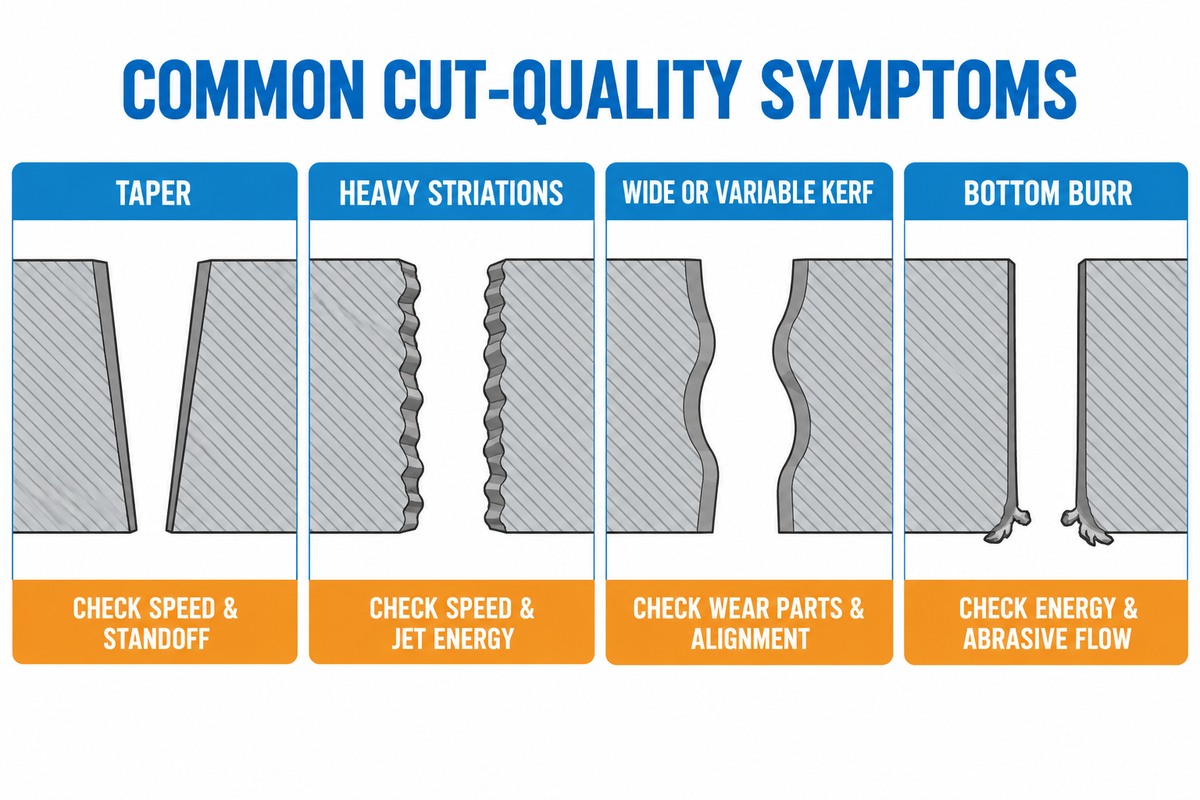
Follow the cutting-head manufacturer’s instructions when checking the water-only stream, centering or replacing components. A coherent stream should not fan out immediately below the nozzle. If the stream is visibly angled, split or unstable, stop and correct the cause before abrasive cutting. Confirm that the orifice and mixing tube are the approved pair for the pump flow and cutting head rather than selecting parts by appearance.
Use a Fixed Troubleshooting Order
A fixed sequence prevents one adjustment from hiding another fault. It also creates a record that production, maintenance and technical-support teams can understand.
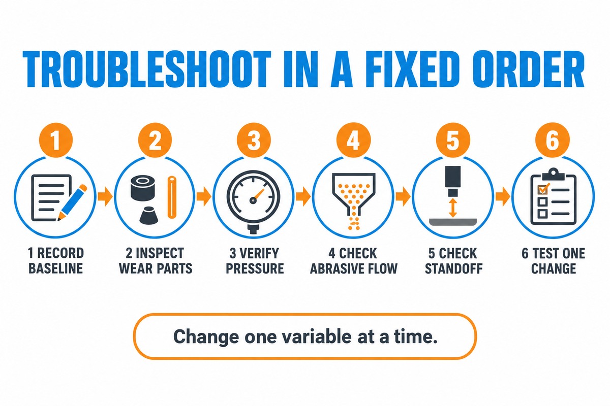
- Record the baseline. Save the program, material data, measured thickness, pressure behavior, abrasive information, wear-part sizes, standoff and photographs.
- Inspect the cut and wear parts. Determine whether the issue is at the entry, wall, exit or geometry transition. Check the orifice, mixing tube, mixing chamber and assembly condition.
- Verify pressure and water supply. Confirm that actual pressure is stable while cutting. Check for leaks, restrictions, filter condition and water quality requirements according to the pump manual.
- Check abrasive delivery. Look for damp or contaminated abrasive, bridging, an obstructed line, inconsistent metering, an incorrect mesh, or timing problems.
- Check standoff, alignment and support. Confirm a flat, stable workpiece, correct height control, cutting-head calibration and appropriate nozzle clearance.
- Make one controlled test. Cut a standard coupon after changing one variable. Measure kerf, taper and edge condition, then record the result before the next change.
Build a Repeatable Test Coupon
A standard coupon is more useful than judging random production parts. Include a straight line, an outside corner, an inside corner, a small circle appropriate for the process, and a pierce. Use the same known material and thickness whenever possible. Mark the top, bottom, cut direction and date. Measure top and bottom kerf width at consistent locations and photograph the full wall under similar lighting.
Keep results with consumable changes and maintenance records. A gradual increase in kerf or a rising transition zone can then be detected before parts fail inspection. This record also helps distinguish a motion or programming problem from a pump, abrasive or cutting-head problem.
Frequently Asked Questions
Do striation marks always mean the feed rate is too high?
No. Higher feed relative to available cutting energy is a common cause, but reduced pressure, interrupted abrasive flow, nozzle wear, alignment problems, excess standoff and incorrect material data can produce similar symptoms. Verify the process before changing speed.
Can a 5-axis cutting head remove all taper?
A calibrated compensation head can significantly reduce taper on the finished edge by tilting the jet toward the scrap side. The result still depends on stable pressure, correct consumables, process data, standoff, calibration and suitable path control. It is not a substitute for basic maintenance.
Why did the kerf become wider even though the program did not change?
Gradual mixing-tube wear is a common reason, but inspect alignment, orifice condition, standoff, pressure stability and abrasive feed as well. Compare a standard coupon with the last known good measurement before changing tool offset.
What information should I send for remote troubleshooting?
Send clear photos of the top, bottom and full cut face; material and measured thickness; pump and commanded/actual pressure; head type; orifice and mixing-tube sizes and hours; abrasive mesh and feed setting; standoff; programmed quality or feed rate; pierce method; and a short video showing pressure and abrasive behavior if safe to record.
Need Help Diagnosing a Waterjet Cut?
YH WATERJET can review your cut-surface photos, process data and cutting-head configuration to help narrow the likely cause and define the next test. Include the material, thickness, pressure, abrasive, wear-part sizes, standoff and program quality setting so the advice is based on evidence.
Contact YH WATERJET